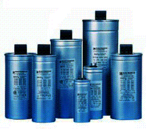
Capacitors Bank
ACTIVECAP Real Time Capacitor Bank
Typical
Applications
|
● Industrial applications: |
|
|
Compressors |
Paper mills |
|
Mining shovels |
Induction furnaces |
|
Saw mills |
Steel rolling mills |
|
Mine hoists |
Petroleum pumps |
|
Water pumping stations |
Wood chippers |
|
Container cranes |
Ski lifts |
|
Nuclear power research |
Auto manufacturing |
|
|
|
|
●
Power
distribution applications: |
|
|
|
Generator load dropping Large loads on weak systems Power transfer increase in
transmission Loss of line contingencies |
||
|
●
Single
phase load balancing application: |
||
|
Single phase automatic welders
Single phase traction systems Product Description |
||
|
A ACTIVECAP
Real Time Capacitor Bank is a micro-processor control, high speed, power
device that controls the voltage or power factor in an electrical
system. Using state of the art
thyristor switching technology power capacitor steps are rapidly switched
(typically 20-500ms) out of the network in response to continuously changing
load conditions. With appropriate control, the voltage, power factor, load
balance or a combination of these variables is kept within close tolerance to
predefined user selectable limits. |
||
|
● Compensation
in Modular Form |
|
Thyristor switched capacitors
are available to the electrical distribution and industrial engineer in the
form of building block modules.
High speed, transient-free, solid state switching of power capacitor
banks is now available as a standardized self-contained unit easily
integrated into existing distribution or industrial power systems. This product provides high speed
voltage regulation or power factor correction. By virtue of its modular design, ACTIVECAP can be built using as many
capacitor steps as required for the particular application. As the load
grows, expansion of the compensation equipment can easily follow by addition
of further capacitor steps. |
|
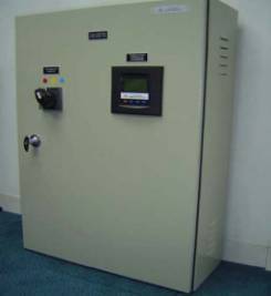
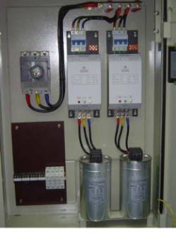
● Construction |
|
Typical ACTIVECAP Real Time Capacitor Bank construction
consists of a number of ACTIVECAP Switching Controllers, capacitor steps and
a ACTIVECAP Intelligent System Controller. Accessories include main isolator
or circuit breaker, main copper busbars, and control components. |
|
How a ACTIVECAP Real Time Capacitor Bank improves economics |
|
|
An alternative to additional capital expenditure is to add compensation to increase the capacity of existing distribution stations: |
|
|
● Reducing voltage fluctuations, reactive power flow and harmonics, enhances stability and reliability of the electrical plant distribution. Neighboring consumers will also experience improvement is the quality of power. |
|
|
● Keeping the power factor close to unity reduces power factor penalty charges and enhance energy saving. |
|
|
● Providing additional voltage capacity during heavy motor starting conditions, costly downtime due to under-voltage tripping is prevented. |
|
|
● Load balancing single phase loads in three phase networks increases available capacity of existing distribution systems. |
|
|
● Allowing simultaneous operation of electrical machinery increases industrial production output. |
|
|
● No arcing occur during switching of capacitor steps lengthens the
services life of capacitor units. |
|
|
Advantages
of ACTIVECAP |
|
�.
● Response time of 20 �. ● Resolution of 1% in voltage �.
● Repetition rate of 20 �. ● No inrush currents �.
● No inrush transients ● No switching harmonics |
|
Installation |
|
Installation is simplified by the use of pre-engineered modular units and the complete testing performed on every ACTIVECAP system before shipment. Estimated installation 1-2 days. Complete installation and operation manuals are provided. ACTIVECAP can be delivered for on-site installation or factory installed and tested in a pre-fabricated transportable modular building. |
|
Diameters of
Connecting Cables and Fuse Ratings for Power Factor Correction |
|
● Protection by Fuses Connection |
|
Where external protection of
the capacitor units from long-term overloading or short-circuiting is to be
provided, a value between 1.43 and 1.8 times rated current should be adopted.
The fuses should be of the slow-blowing type owing to the high momentary
current at make. |
|
Output Unit/ Equipment
(kVAr) |
Rated Capacitance (µF) |
Rated Current (Amps) |
Cross section for 4/C Cu
cable (mm2) |
Fuse Current Slow-blow
(Amps) |
|
10 |
3 x 66.3 |
14.4 |
4 |
25 |
|
12.5 |
3 x 82.9 |
18.0 |
6 |
35 |
|
15 |
3 x 99.5 |
21.6 |
6 |
35 |
|
20 |
3 x 132.6 |
28.8 |
10 |
50 |
|
25 |
3 x 165.8 |
36.1 |
16 |
63 |
|
30 |
3 x 198.9 |
43.3 |
25 |
80 |
|
40 |
3x 265.3 |
57.7 |
35 |
100 |
|
50 |
3 x 331.6 |
72.1 |
50 |
125 |
|
60 |
3 x 397.6 |
86.6 |
70 |
160 |
|
70 |
3 x 464.2 |
101 |
70 |
160 |
|
90 |
3 x 596.8 |
130 |
120 |
250 |
|
100 |
3 x 663.1 |
144 |
120 |
250 |
|
125 |
3 x 828.9 |
180 |
185 |
300 |
|
150 |
3 x 994.7 |
217 |
240 |
315 |
|
180 |
3 x 1193.7 |
260 |
240 |
400 |
|
200 |
3 x 1326.3 |
280 |
240 |
400 |
|
250 |
3 x 1657.9 |
361 |
240 |
400 |
|
300 |
3 x 1989.4 |
433 |
400 |
630 |
|
Connecting cables should be designed for 1.5 times the rated current values and upwards. |
|
The diameter for cables and the fuse
ratings are minimum values valid for operation under normal conditions and at
an ambient temperature of |
|
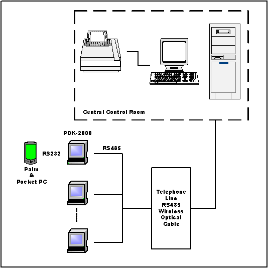
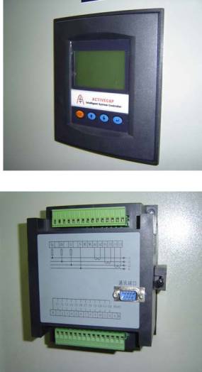
Features
of ACTIVECAP Intelligent System Controller |
|
This controller serves as a central power
analyzer which measures a large number of parameters including harmonics up
to the 13th. |
|
Measurement |
|
|
|
● 3 phase voltage / current / power factor ● kW / kVar ● kWh / kVarh ● Hz / harmonic voltage / harmonic current ● Maximum and minimum current ● Duration of power failure ● Time of power failure ● Time of power restoration ● Accumulated time of power failure ● Maximum and minimum voltage ● Phase failure ● Harmonic analyze up to 13th ● Data storage for 60 days Communication ● RS232 or 485 ● 1200, 2400, 4800, 9600bps selectable ● On site or remote data collection ● Real time or set time for data collection
●
Support Windows 9X for data reporting
in table, curve or bar chart format Protection ● Over / under
voltage or harmonic order over setting limit will trip all the capacitor
steps |
|
|
|
Display ● 128x ● Real time display power system parameters
● Direct reading of data setting |
||
|
Working
environment ● Working temperature : -25oC / +55oC ● Humidity at 20oC : 95% ● Latitude : ≤ ● Environment : no risk of explosion, corrosive metal gases and
conductive dusts |
||
|
Specification ●
Rated voltage ● Frequency ●
Input
voltage ● Input current ● Internal losses |
: 220Vac +/- 20% : 50Hz +/- 5% : 220Vac +/- 20% :
3x0~ :
≤15W |
|
|
Control
Parameters |
|
|
● Selection |
:
Auto / Manual |
|
● sensitivity |
: 100mA |
|
● cosØ
setting |
: 0.85~1, interval 0.01, factory set
0.98 |
|
● K
factor |
: 0.6~1.6, interval 0.1, factory set 1.1 |
|
● Switching
time delay |
: Dynamic 20~500ms Static 1~100s Factory
set 30s |
|
● Over-voltage
protection |
:
240~260V, interval 5V, factory set 245V |
|
● Under-voltage
protection |
:
180~150V, interval 5V, factory set 165V |
|
● Harmonic
setting |
:
5%~20%, interval 0.5%, factory setting 10% |
|
● Zero
sequency setting |
:
5%~60%, interval 5%, factory setting 25% |
|
● Output
terminal |
:
12 steps 12Vdc
for ACTIVECAP switching modules |
|
Accuracy |
|
|
|
● Voltage |
: +/- 0.5% |
|
|
● Current |
: +/- 0.5% |
|
|
● Power
factor |
: +/- 1.5% |
|
|
● kW |
: +/- 1.0% |
|
|
● kVar |
: +/- 1.5% |
|
|
● kWh |
: +/- 1.0% |
|
|
● kVarh |
: +/- 1.5% |
|
|
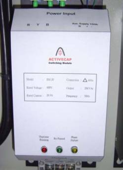
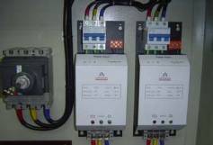
Features
of ACTIVECAP Switching Module |
|
ACTIVECAP switching module is the most advance capacitor
step switching device. This
module makes use of the combination of thyristors and electromechanical
contactor to give the most
advancing technologies to achieve the best performance of switching mechanism
and to improve the services life of switching devices. |
|
Working Principal |
|
When the switching modules receive an external switching
signal, it will automatically search for the optimum timing for switching in
capacitor steps and guarantee at zero point cut-in, no transients, no arcing,
low losses, no harmonics, over/under voltage and phase failure protection. An indicating lamp is provided
to shows it’s working conditions. The
thyristors and electromechanical contactor is connected in parallel. A
micro-processor will detect the system parameters and make sure the
thyristors conduct at zero voltage and cut-out at zero current. This module fully usable of the
advantages of thyristor switching technologies After conducting and system in stables
conditions, the electromechanical contactor will energize to bypass the
thyristors. When switching out is
necessary, thyristors will cut at zero current after the contactor dropping
out. Because the switching occur
at zero, no harmonics will be generated. If
there are any under / over-voltage or phase failure, the module will refuse
to cut in or cut out automatically. The application of the
electromechanical contactor, control component consume power only at
switching condition, no power will be consumed at rest conditions. Hence, it greatly reduces the power
losses resulting less heat generation and lengthen the services life of the
thyristors. Besides, the input signal and switching modules is
galvanic isolation, no interference to each other will occur. |
|
|
||
|
● Zero point switching, no transient ● Long service life ● Low loss ● No harmonic generated |
|
|
|
Specification |
|
|
|
Rated voltage |
: 220/380Vac +/- 20% |
|
|
Switching frequency |
: 100,000 times |
|
|
Maximum capacitor |
: ≤30kVar (power loss ≤1.5VA) |
|
|
Switching time interval |
: 1s |
|
|
Energizing voltage |
: 12Vdc |
|
|
Safety protection |
: power faialure and single phasing, refuse to cut-in or cut-out automatically |
|