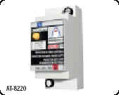
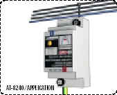
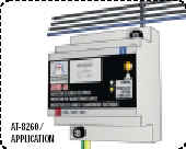
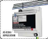
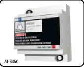
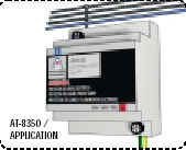
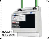
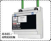
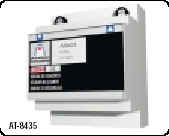
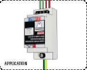
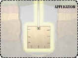
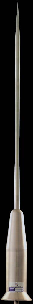
Lightning Protection

Cause of Lightning Main

¡@

LIGHTNING Conductor¡@

DAT-CONTROLER®

Lightning formation is preceded by an increase, higher than 10 KV/m, in the ambient electric field. This natural energy is directly accumulated by the triggering device of the DAT-CONTROLER® lightning conductor, which automatically turns into pre-control situation.

Lightning discharge approach provokes an intense and sudden increase of the electric fields, thus originating a lightning strike risk area. If this risk area takes place in the zone protected by the DAT-CONTROLER®, the sudden variation of the electric field simultaneously actions the control system of the DAT-CONTROLER® which, in synchronization with lightning approach, provides the safest controlled discharge path to earth.

Atmospheric electric field as its only power supply. Totally autonomous and maintenance free. Functioning can be tested at any moment.


CHARACTERISTICS:

Early Streamer Emission lightning conductor which:

  1. Fulfils Standards UNE 21 186 and NF C 17-102
  2. Radius of protection certified for each model and level.
  3. Gain in triggering time values specific for each model.
  4. Effective performance in weather condition.Insulation superior to 95%.
  5. Effective full operation after being submitted to several lightning currents.


EFFECTIVITY:

Effective performance tests by:

  • LCOE - Central Official Electrotechnics Laboratory - Ministry of Industry and Energy (Madrid).
  • SEDIVER - High Voltage Laboratory of Bazet (France).
  • Faculty of Physics, University of Valencia (Spain).
  • Institute of Electric Technology (ITE), Polytechnic University of Valencia (UPV) (Spain).
  • AIMME - Technologic Metal-Mechanic Institute (Spain).
  • EDF - Electricité de France - High Voltage Laboratory Les Renardières (France).
  • BET - High Voltage Laboratory of Blitzschutz & EMV Technologiezentrum (Germany).


LEVEL OF PROTECTION:

For the design of any External Lightning Protection Installation a prior survey should be conducted to determine the protection level to be considered, the Early Streamer Emission lightning conductor location(s), the down-conductor path(s), the earth termination system location(s) and type(s). The main part of this survey is the direct strike risk calculation. The higher risk, the higher required protection measures (for a very high risk, LEVEL I OF PROTECTION, for a medium risk, LEVEL II OF PROTECTION and for a standard risk LEVEL III OF PROTECTION).

For the maximum safety, Standard UNE 21 186 and APLICACIONES TECNOLOGICAS, S.A. recommend LEVEL I OF PROTECTION.


The normative Annexe B of Standards UNE 21 186 and NF C 17-102 constitutes the LIGHTNING RISK ASSESSMENT GUIDE AND SELECTION OF PROTECTION LEVEL.

¡@

¡@

LIGHTNING EVENT COUNTER

REF. CHARACTERISTICS
AT-00G Galvanised Iron support for counter to guard tube fixing
AT-01G Registers the number of storks of lightning received by the lightning protection system

SURGE PROTECTIVE DEVICES

SINGLE/ COMBINED PROTECTION
REF. DESCRIPTION I8/20 Ures
AT-8112 ATCOVER 220M Two-pole protection for 220V single-phase lines 20KA <900V
AT-8133 ATCOVER 380T Four-pole protection for 380V three-phase lines 20KA <900V
AT-8111 ATCOVER 130M Two-pole protection for 130V single-phase lines 20KA <700A
AT-8132 ATCOVER 220T Four-pole protection for 220V three-phase lines 20KA <700A

¡@

PROTECTION BY ZONES
REF. DESCRIPTION I8/20 Ures
AT-8220 ATSUB 20 One-pole protection for secondary distribution boards 20kA <1,2KV
AT-8240 ATSUB 40 One-pole protection for secondary distribution boards 40kA <1,4KV
AT-8260 ATSUB 60 One-pole protection for secondary distribution boards 60kA <1,6KV

¡@

PROTECTION BY ZONES / COMBONED PROTECTION

REF. DESCRIPTION I10/350 Ures
AT-8350 ATSHOCK L One-pole protection for high currents (Phase/Earth) 100kA <4KV
AT-8399 ATSHOCK N One-pole protection for high  100kA <4KV

¡@

PROTECTION BY ZONES / COMBINED PROTECTION
REF. DESCRIPTION Working current
AT-8435 ATLINK 35 Decoupling inductor for SPD co-ordination 35A
AT-8463 ATLINK 63 Decoupling inductor for SPD co-ordination 63A

¡@

PROTECTION OF TELEPHONE LINES
REF. DESCRIPTION I8/20 Ures
AT-9101 ATFONO Two-pole protection for standard / ADSL telephone lines 20kA <330V

¡@

PROTECTION OF DATA LINES
REF. DESCRIPTION I8/20 Ures
AT-9205 ATLINE 5 Two-pole protection for 5VDC data lines 20kA <10V
AT-9212 ATLINE 12 Two-pole protection for 12VDC data lines 20kA <24V
AT-9215 ATLINE 15 Two-pole protection for 15VDC data lines 20kA <30V
AT-9224 ATLINE 24 Two-pole protection for 24VDC data lines 20kA <48V
AT-9230 ATLINE 30 Two-pole protection for 30DC data lines 20kA <60V
AT-9248 ATLINE 48 Two-pole protection for 48VDC data lines 20kA <96V

PROTECTION OF TV SIGNAL LINES
REF. DESCRIPTION I8/20 Ures
AT-2101 ATCOAX Protection for analogue TV signal 20kA <1KV

¡@

CLAMP

HANDLE CLAMPS

¡@

REF.  Characteristics
AT-50N   Universal clamp for graphite moulds
AT-51N  Specific clamp for large conductors

¡@

EXOTHERMIC WELDING
APLIWELD is a welding system that employs an exothermic reaction to obtain on-site, homogeneous connections among conductors.

The procedure consists of fixing the conductors to be welded using a graphite mould. Welding mixture and starting powder are also placed inside this mould. When a spark is applied, it starts the reduction of the copper oxide by the aluminium. this reaction is highly exothermic, thus reaching a high enough temperature to melt both the preparation and the conductors. The whole mass therefore becomes homogeneously welded. The conductivity of the connection is the same or even higher than in the conductors, being able to stand high currents and avoiding corrosion problems that could appear with simple mechanical joints.

The graphite mould is semi-permanent and specific to each of the conductors to be welded. The amount of welding mixture must also be selected according to the welding size desired. When conductors are welded, the mould is opened using the handle clamps and cleaned, being then ready for another welding.

As it has no need for an external energy supply, the process is totally autonomous. This, together with electrical, mechanical and corrosion-resistance characteristics makes it especially suitable for welding conductors forming part of the external lightning protection system, as well as for any earth termination system.

¡@

INSTRUCTIONS OF USE

1. Pre-heat the mould and the conductors to be welded during a sufficient period of time using a welding torch. Place the conductors inside the corresponding holes in the mould. 2. Once the mould is closed and fixed by the clamps, place the tin disk at the bottom of the crucible, thus avoiding the loss of welding powder. 3. Pour the welding powder into the crucible cover it and its borders with enough starting powder.
4. After closing the security lid, light the starting powder using a flint gun, welding torch or flare. 5. The exothermic reaction takes place. It is recommendable of fasten the mould, firmly holding the clamps during the process and not to stay too close to the spark outlet hole. 6. Wait for 1 minute before opening the mould and the final welding will have be obtained. Clean the mould with the proper tools. If the mould is still hot, it can be used for another welding without pre-heating.

MOULDS

REF. CHARACTERISTICS
CABLE TO CABLE
C50/C50/11 Straight union, 50mm2 stranded or Ø8mm solid round
C50/C50/12 "T" Union, 50mm2 stranded or Ø8mm solid round
C50/C50/15 Parallel union, 50mm2 stranded or Ø8mm solid round
TAPE TO TAPE ¡@
P302/P302/21 Straight union, 30X2 mm tape
P302/T18/64 "T" union, 30X2 mm tape
P302/P302/23 Cross-shaped union, 30X2 mm tape
"T" UNIONS, WITH EARTH RODS
C50/T14/64 "T" union, 50mm2 cable to Ø 14mm earth rod
C50/T18/64 "T" union, 50mm2 cable to Ø 18mm earth rod
P302/T14/71 "T" union, 30X2 mm tape to Ø 14mm earth rod
P302/T18/71 "T" union, 30X2mm tape to Ø 14mm earth rod
OTHER UNIONS
C50/V40/52 50mm2 stranded or Ø 8mm
¡@ solid round to Re-bar Ø 40 mm

WELDING MIXTURE

WELDING COMPOUNDS IN SINGLE-DOSE PACKAGES
REF. DESCRIPTION AMOUNT
E32 32 gr welding compound package 10 unit box
E45 45 gr welding compound package 10 unit box
E65 65 gr welding compound package 10 unit box
E90 90 gr welding compound package 10 unit box
E115 115 gr welding compound package 10 unit box
E150 150 gr welding compound package 10 unit box
E200 200 gr welding compound package 10 unit box
E250 250 gr welding compound package 10 unit box

¡@

GROUND ENHANCING PRODUCTS

REF. DESCRIPTION
AT-10L Conductiver Plus. Non-corrosive and ecological gel that improves soil conductivity
AT-20L Graphite powder, specific for earth termination system (30kg bag)
AT-30L Thin clay-like powder, specific for earth termination systems (25kg bag)

Top of the page